The Importance of Lead Length for Arrester Applications
Take a closer look at the impact of lead length, a commonly overlooked consideration in arrester applications.

 A commonly overlooked consideration in arrester applications is the impact of lead length. The inductance of lead wires can produce an inductive voltage drop which in turn will lower system protection. This voltage drop only occurs if the lead carries surge current and is in parallel with the equipment being protected. This resultant voltage is added to the discharge voltage of the arrester during a surge event, thereby reducing the protective margin of the system. The lead wire’s inductance is not strongly influenced by conductor diameter, but rather of overall lead length. Therefore, care must be taken to keep the lead length to a minimum in both distribution and substation applications.
Distribution Arrester Applications
In distribution applications, strength of the lead wire is rarely a concern so AWG #4 – #8 wires are commonly used. When considering arrester lead length, both the line and ground leads must be considered when in parallel to the protected equipment and carrying surge current. Another unique consideration for distribution applications is the use of a ground lead disconnector (GLD). If a GLD is used in the application, then the ground lead should be sized to provide enough clearance for the disconnector to operate and isolate the arrester from ground in the case of arrester failure.
Substation Arrester Applications
Substation applications have other considerations when evaluating placement of arresters and leads or buswork. First, there may be mechanical requirements of either the line or ground connections of the arrester. In this case, the conductor should be sized to meet those requirements, but keeping the overall length to a minimum. Things like load application and seismic activity might also influence the conductor size. Also, just like for distribution, the lead length includes all leads that are in parallel to the protected equipment and carry surge current. This means that separation distance, or the distance the arrester is placed from the protected equipment, is very important as that lead length will need to be accounted for as well.
Sample Calculation
This example calculation simulates the lead length effects on insulation coordination for a distribution application. Similar examples with protective margin calculations can also be found in the IEEE C62.22 or IEC 60099-5 application guides.
Transformer Characteristics:
- 95 kV full-wave withstand (BIL)
- 110 kV chopped-wave withstand (CWW)
Arrester Characteristics (10.2 kV MCOV):
- 6 kV Lightning residual voltage @ 10 kA
- 1 kV Front of Wave residual voltage @ 10 kA
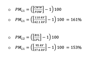
Without considering the inductive voltage drop due to lead length
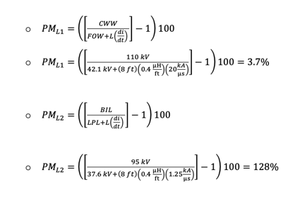
Including the lead length effect
- First calculate total lead length ≈ 8 ft
- Assume inductance of 0.4 µH/ft
Recommended Posts
.png?width=767&name=ACL-HPSUA-GR-EN-04290%20(1).png)
How Utilities Use Capacitor Banks for Volt-VAR Optimization

Common Misconceptions About URD Grounding — and What You Should Know
