How to Use Power-Installed Screw Anchors
The Power Installed Screw Anchor (PISA®) wrench transmits torque from the digger’s Kelly bar to the anchor hub. Note: The anchor rod only has to be of sufficient diameter to support the guy load.

"Proper alignment" and "down pressure" are simple phrases to summarize proper anchor installation technique. The Power Installed Screw Anchor (PISA®) wrench transmits torque from the digger’s Kelly bar to the anchor hub. Note: The anchor rod only has to be of sufficient diameter to support the guy load.
Always maintain adequate down pressure and keep the Kelly bar and the wrench aligned with the anchor. The right amount of down pressure keeps the anchor continuously advancing. Too much down pressure may bend or even break an anchor helix at torque loads far below the rating. Too little down pressure may result in “churning” the soil, damaging the wrench and possibly the digger truck. Either extreme may result in wasted time, reduced holding capacity and damaged equipment.
FOR SITUATIONS WHERE OVERHEAD LINES ARE NOT AN OBSTRUCTION: STEP-BY-STEP ANCHOR INSTALLATION PROCEDURE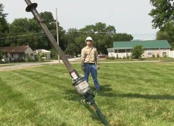
The Kelly bar adapter is attached to digger’s Kelly bar by a single bolt. The Locking dog assembly holds the drive end assembly. If an anchor depth of one 7’ rod length is desired, drive end assembly is all that is required. If the anchor is to be installed deeper than one anchor rod length, the 3-1/2’ extension assembly is attached between the drive end assembly and the locking dog assembly to obtain added depth. PISA® anchors should not be installed beyond 14’ since wrench retrieval is difficult beyond this depth.
STEP ONE – OPEN LOCKING DOGS
Before installing the drive end assembly in the locking dog assembly, open dogs by pulling outward and twisting to the outside position. NOTE: Locking dog assembly has three ring positions. The middle position holds the wrench drive end assembly. The inside ring position allows locking dogs to hold the anchor rod. The outside position releases drive end assembly from locking dog assembly.
STEP TWO – INSERT DRIVE END ASSEMBLY
With locking dog rings in the outside position, insert drive end assembly into the locking dog assembly. Rotate rings to the middle position. Drive end assembly will be captured in locking dog assembly. Now rotate locking dogs to the inside position to accept and capture the anchor rod.
STEP THREE – INSERT ANCHOR ROD – IN DRIVE END ASSEMBLY
The assembly will hold the anchor rod now that the locking dog is at the inside position. Screw rod into the threads located in the hub of the anchor helix. Insert the rod into the drive end assembly with an upward thrust.
STEP FOUR – LOCKING ANCHOR IN PLACE
With strong upward motion, lock the anchor into the wrench. Locking dogs that are properly closed to the inside position will hold the anchor rod in wrench.
STEP FIVE – INSTALL ANCHOR
First, place the anchor in a near vertical position. When the anchor has a good start, retract the boom to correct anchor angle. Complete installation. During installation, truck outriggers should lift slightly. Avoid excessive uplift. Stop installation when the locking dogs reach ground level.
STEP SIX – RETRIEVE WRENCH
Position the locking dog rings in the middle position and withdraw wrench. The anchor rod will remain in the ground.
STEP SEVEN – ATTACH ANCHOR EYE NUT
For an installation deeper than one anchor rod length, perform the following steps:
- REMOVE LOCKING DOG ASSEMBLY AT GROUND LEVEL – Position locking dog rings in the outside position and withdraw the locking dog assembly.
- ADD ANCHOR ROD EXTENSION – Add anchor extension rod to the rod remaining in ground.
- ATTACH WRENCH ASSEMBLY – With wrench extension bolted to the drive end assembly in the ground and locked in position at the locking dogs, installation can proceed.
- COMPLETE THE INSTALLATION – When locking dogs reach ground level, position locking dogs in the middle position and retrieve the drive end assembly and extension assembly. Attach the anchor eye nut and the installation is complete.
NOTE: Always refer to the supplied tooling instructions before any installation as conditions may require a modification in practiced methods.

Recommended Posts
.png?width=767&name=ACL-HPSUA-GR-EN-04290%20(1).png)
How Utilities Use Capacitor Banks for Volt-VAR Optimization

Common Misconceptions About URD Grounding — and What You Should Know
