Why VARs and Power Factor Matter in Utility Distribution Networks
Learn how VARs, reactive power, and power factor impact distribution system efficiency, voltage performance, losses, and feeder capacity
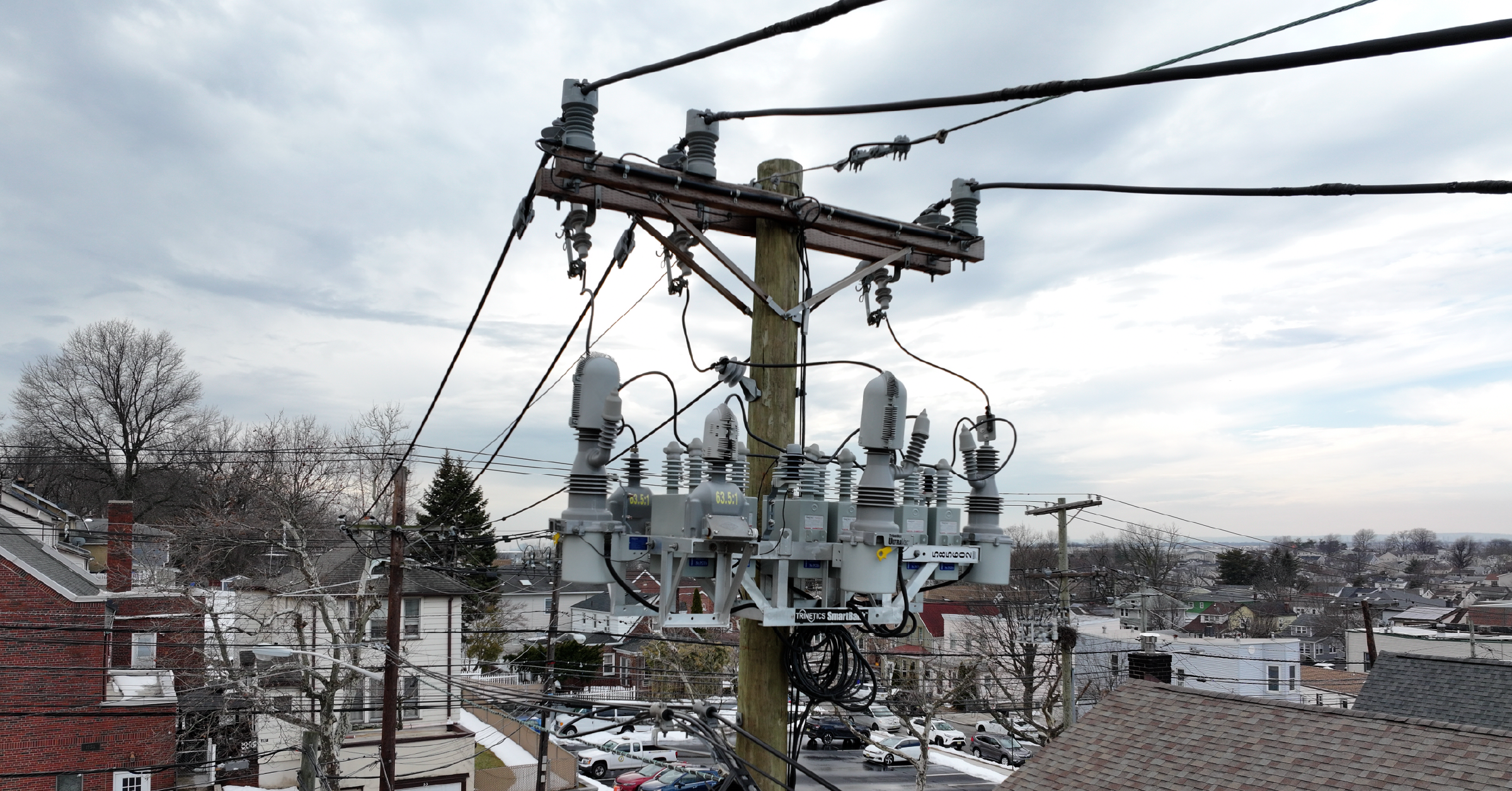
Distribution feeders are often pushed toward their operational limits, whether due to increasing load demand, longer circuits, or evolving grid conditions. In many cases, utilities observe greater voltage drop, higher losses, or reduced available capacity, even when the actual load demand (kW) has not significantly changed. In these situations, the challenge is not always how much power is being used, but how efficiently that power is being delivered through the system. To understand this, it is important to look beyond real power and examine the role of reactive power (VARs) and power factor in the system.
Understanding Power in the Distribution System
Electrical energy is generated at power plants and transmitted over long distances at high voltages. At distribution substations, transformers reduce the voltage to medium-voltage levels (typically 34.5 kV and below), where distribution feeders carry power to residential, commercial, and industrial customers.
The Power Triangle
The total power flowing through a distribution system is referred to as apparent power (kVA). This consists of two components:
- Real (active) power, kW: the portion that performs useful work such as lighting, heating, or mechanical motion
- Reactive power, kVAR: the portion required to support electric and magnetic fields in equipment such as motors and transformers
These three quantities—kW, kVAR, and kVA—are commonly represented using a power triangle, which illustrates how real and reactive power combine to form the total system demand.
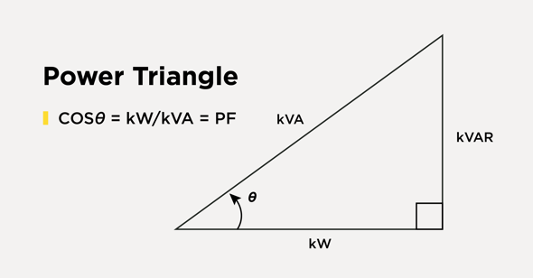
Figure 1 – Power Factor Triangle
What Are VARs?
Reactive power, measured in volt-amperes reactive (VARs or kVAR), does not directly perform useful work such as turning a motor shaft or powering equipment. Instead, it plays a critical supporting role in the operation of the electrical system.
Reactive power is required to establish and maintain the magnetic and electric fields that allow inductive equipment—such as motors, transformers, and many industrial loads—to operate properly. This energy is not consumed in the traditional sense; instead, it continuously moves back and forth between the source and the load.
While reactive power is essential, excessive reactive power in the system can reduce overall efficiency and increase the burden on electrical infrastructure.
What Is Power Factor?
Power factor (PF) is a key metric for understanding how efficiently electrical power is being used in a system. It is the ratio of real power to apparent power, defined as:
Power Factor = kW / kVA
Equation 1 – Power Factor
A power factor close to 1.0, unity, indicates that most of the supplied power is being converted into useful work. A lower power factor indicates that a larger portion of the total power is circulating as reactive power.
For a given load, the real power requirement (kW) is largely determined by the work being performed. However, the apparent power (kVA)—and therefore the total current that must be carried by the system—can increase significantly depending on the level of reactive power present.
In most distribution systems, power factor (PF) is lagging, which means that the current waveform slightly lags the voltage waveform. Lagging power factor is caused by inductive loads. Capacitor banks supply leading reactive power, helping to offset this condition. Leading power factor can also occur with long underground circuits.
Where Poor Power Factor Occurs and Why It Matters
Poor power factor is commonly observed in distribution systems with significant reactive power demand, including motor-heavy industrial loads, lightly loaded transformers, long feeders, and systems with dynamic loading conditions.
Because of the additional current required to support uncompensated VARs, a poor power factor can result in:
- Higher technical (thermal) losses
- Increased voltage drop
- Reduced system capacity
One valuable way to view the relationship of PF to system capacity and total load that must be served is to rearrange the power factor equation to:
kVA = kW / Power Factor
Equation 2 – Total Power Based on Real Power and PF
Looking at it this way, it becomes clearer that for a given amount of Real Power to be served, how much the Total Power increases on the system or substation transformer based on poorer and poorer levels of power factor.
|
Load (MW) |
Power Factor |
Required Total Power (MVA) |
Add’l Capacity Required |
|
10 |
1.0 (unity) |
10 |
-- |
|
10 |
0.98 |
10.20 |
2% |
|
10 |
0.95 |
10.53 |
5.3% |
|
10 |
0.90 |
11.11 |
11.1% |
|
10 |
0.85 |
11.76 |
17.6% |
Equipment such as transformers and conductors must be sized based on kVA, not kW, meaning inefficient systems require more infrastructure to deliver the same useful power.
Some system providers have contractual obligations or rate structures associated with maintaining a minimum power factor, with thresholds typically between 0.85 to 0.98.
Improving Power Factor with Capacitor Banks
One of the most effective methods for improving power factor is the use of capacitor banks. These devices supply reactive power locally, reducing the burden on upstream systems and improving efficiency.
The Role of VAR Management in Grid Efficiency
Power factor is a critical measure and lever for improving efficiency, maximizing system capacity, and maintaining reliable grid operation. By effectively managing reactive power and power factor, utilities can reduce losses, improve voltage performance, and optimize infrastructure utilization.
For more information, explore our turnkey key power factor correction and capacitor bank solutions.
Recommended Posts
.png?width=767&name=ACL-HPSUA-GR-EN-04290%20(1).png)
How Utilities Use Capacitor Banks for Volt-VAR Optimization

Common Misconceptions About URD Grounding — and What You Should Know