Project Example – Using Helical Capacity Design Software for Helical Pile Foundation Bid
An in depth explanation of how an engineer or contractor can use HeliCAP software to create an accurate helical pile design and bid for deep foundations.

We’re often asked by engineers and contractors how to bid helical pile foundations. This often happens when the geotechnical report for the project does not provide specific recommendations for the helical piles, i.e., pile type and length, helix configuration, and capacity. One of the best tools available to design helical piles based off a geotechnical report is HeliCAP® v3.0 Helical Capacity Design Software. The soil boring information can be taken directly from the geotechnical report and input into HeliCAP. Within minutes, the software will provide everything necessary to competitively bid the project.
Create an account and start using HeliCAP
The following example project is the new Hubbell Power Systems, Inc. Customer Service Building located in Centralia, MO. The building is a multi-story structure consisting of offices and meeting rooms. In this example, the Structural Plans call for shallow foundations to support the building columns. Helical Piles are being considered as a deep foundation alternative to a shallow foundation. The Plans call for 35-kip allowable compression load and 2-kip allowable lateral load for the helical piles.
The first step is to review the geotechnical report to check the feasibility of helical piles. See boring B-3 for site characterization data: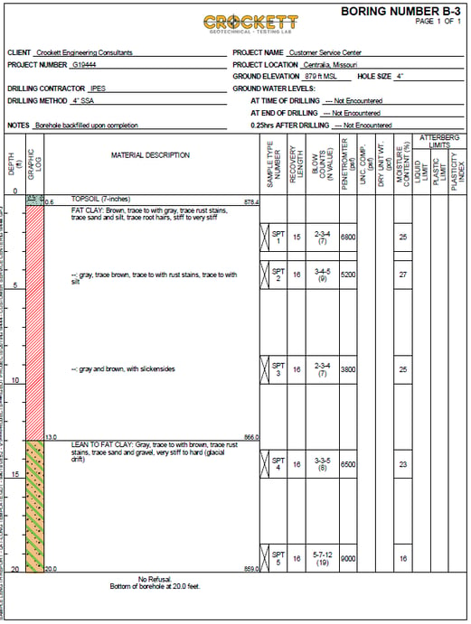 The profile consists of 12-13 feet of stiff to very-stiff clay trending to very-stiff to hard clay glacial drift deposits down to the bottom of the boring at 20 feet depth. The stiff clay trending to glacial deposits is an ideal soil profile for helical piles. The stiff consistency provides lateral support of the shaft and will also resist the required 2-kip lateral load. The question is will the very stiff to hard glacial deposits provide enough bearing capacity to support the 35-kip axial compression load?
Video – Learn how to input a Soil Profile in HeliCAP
This screen shot from HeliCAP. It shows the soil profile taken from bore log B-3:
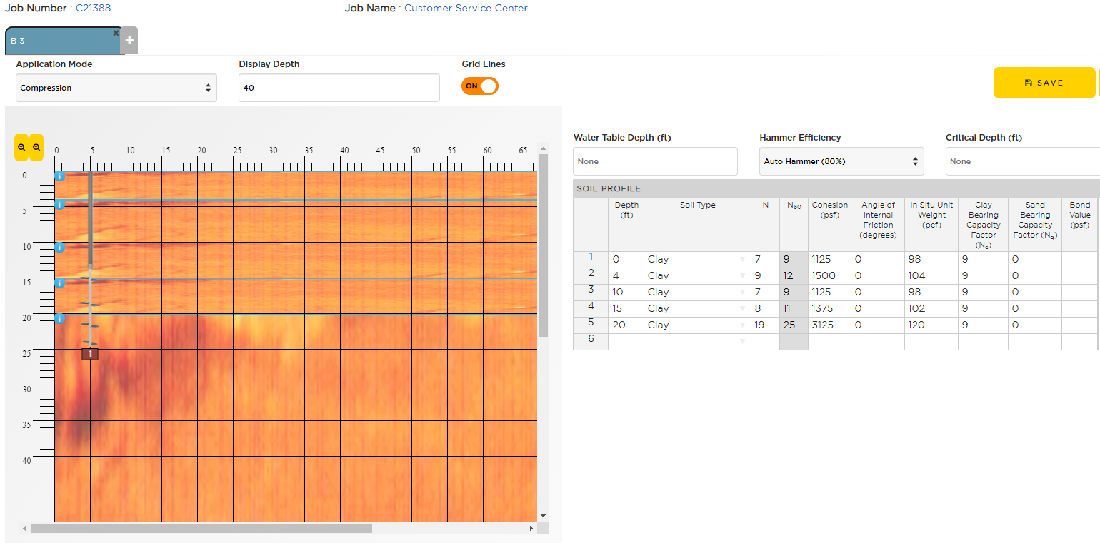
The inputs used were the ASTM D-1586 Standard Penetration Test N-value blow counts recorded for each sounding depth, corrected for the use of an auto-hammer as noted in the Crockett Geotechnical Report. HeliCAP uses SPT N60 blow count correlations to determine the cohesion of the clay and also the unit weight. Once the soil profile is entered, the user can then “configure” the helical pile, i.e., select the pile type, length, installation angle, and helix configuration. Experienced users will generally know which helical pile product type is capable of achieving the specified load requirements. Table 7-4 in the CHANCE Technical Design Manual – 4th Edition is a great way for novices and infrequent users to quickly determine which helical pile type and size will work. For this case, a pipe shaft helical pile is a good choice due to the requirement to resist the 2-kip lateral load.
I chose a CHANCE SS175/RS3500.300 Combo Pile as the pile type for this project example. The SS175 lead section is an effective penetrator of the hard glacial deposit and the 3-1/2” OD pipe shaft RS3500.300 extensions will effectively provide the lateral load resistance, plus effectively transfer the axial compression load down to the helix bearing plates on the lead section. A four-helix configuration (10”-12”-14”-14”) was selected mainly based on past experience in the area. As shown, the four-helix configuration and an overall length of 25 feet will provide an ultimate compression capacity in excess of 73 kip.
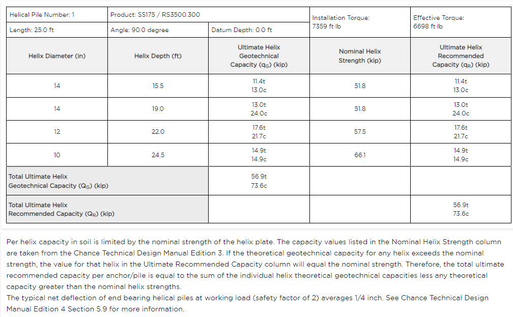
This exceeds the allowable load of 35 kip by more than a factor of two which is typically the minimum factor of safety recommended by Hubbell Power Systems, Inc. for permanent structures. Helical pile net settlement typically ranges between 1/8” and 3/8” at the allowable load when the axial capacity is at least twice the allowable load. Note also that the above picture shows the helical pile in the soil profile, so the user can quickly see where the helix plates are located with respect to the overburden clays and glacial deposits.
Video – Learn how to Insert a Helical Pile in the Soil using HeliCAP
Shown here are plots of the helical pile capacity and the installation torque with respect to depth.
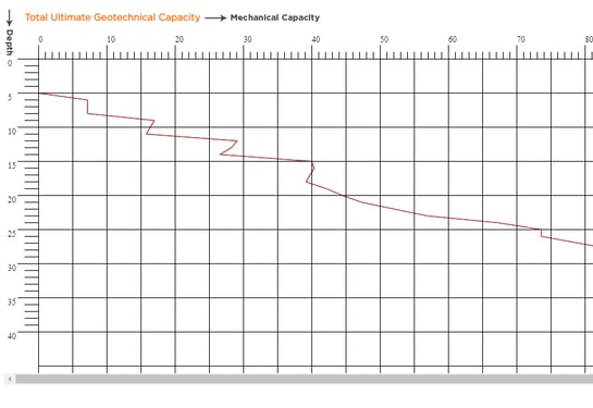
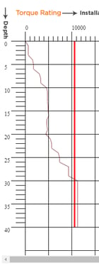
They provide a quick check of both the capacity and torque with increasing depth throughout the soil profile. This is good information for the contractor when the helical piles are installed since it shows the expected trends in terms of installation torque.
We now have enough information to prepare a bid for this project. The following table summarizes the information needed to prepare a bill of material. One very important item is the required installation torque. The minimum installation torque listed in the table below may be different than what is given by HeliCAP, as is the case in this example. That’s because HeliCAP calculates install torque based on the bearing capacity calculations. It’s still good practice to specify the required installation torque based on the default Kt values for the pile type selected, which in this case the Kt is 8.5 for SS175/RS3500 Combo Piles.
|
Pile Type: |
CHANCE® Type Combo Shaft Helical Pile |
|
Shaft Materials: |
Lead Section: Type SS175 (1-3/4” RCS) Solid Square Shaft |
|
Extensions: |
Type RS3500.300 (3.5” O.D. Pipe Shaft w/ 0.300” wall) |
|
Helix Configuration: |
10”-12”-14”-14” diameter helix plates |
|
Bid Length: |
25 feet |
|
Required Capacity: |
35 kip working / 70 kip ultimate – Compression |
|
Minimum Installation Torque: |
8,300 ft-lb |
Recommended Posts

How to Specify Helical Piles: A Practical Guide for Engineers

Streetlight Foundation Design: ASD vs. LRFD Explained
