Why Use “H” Rated Clamps for Temporary Grounding
It is important for utilities to understand the ratings of temporary grounding clamps. H rated clamps offer better protection for linemen.
 Prior to 2009, ASTM F855, Standard Specifications for Temporary Protective Grounds to Be Used on De-energized Electric Power Lines and Equipment only included one table indicating the specifics to which ground set designs were to be tested. This “Table 1” was based on a near symmetrical current, limiting the circuit inductive reactance to resistance (X/R) ratio to a maximum of approximately 1.8 (20% asymmetry). The most recent edition of The Encyclopedia of Grounding has a section on H-Rated Grounding. Download it now.
Still included in the standard today, Table 1 specifies grounding component ratings of Grades 1-7. A rating can be achieved by passing the Withstand requirements or the Ultimate requirements.
Per ASTM F855, the definition of Withstand is: a near symmetrical current which shall be conducted without any component being damaged sufficiently to prevent being operable and reusable. The protective ground shall be capable of passing a second test at this current after being cooled to ambient temperature.
The definition of Ultimate is: a current which it is calculated the component is capable of conducting for the specified time. It is expected that component damage may result. The component shall not be reused, except in test situations.
Get the catalog on H-Rated Grounding
In 2009 ASTM 855 added “Table 2.” This table establishes the values to which grounding components must be tested if they are to be used at grounding locations where the asymmetry is greater than 20% (X/R>1.8). The values in Table 2 represent an X/R ratio of 30 (90% asymmetry).
Table 2 has clamp ratings of 1H – 7H.
Table 2 adds additional mechanical forces with the X/R of 30. All of the thermal stress from Table 1 is still there and even a little more with slightly higher RMS current. The test requirements of Table 2 result in much higher levels of mechanical force acting on the grounding equipment than the requirements of Table 1. Because of the asymmetrical current and high X/R values associated with Table 2, the current waveform is “offset,” and the ground sets will see significantly higher peaks in the first several cycles. The ground sets must survive this initial burst of energy in order to provide worker protection. For example, a Grade 5H clamp is rated at 47kA but must survive a 1st cycle peak of 127kA (or 90% greater than the symmetrical peak) and a 15th cycle peak of 70kA during testing. The two waveforms below indicate the differences in a 31kA current at an X/R of 1.8 and an X/R of 30. You can see the significant increase in magnitude in the first several cycles with the X/R of 30.
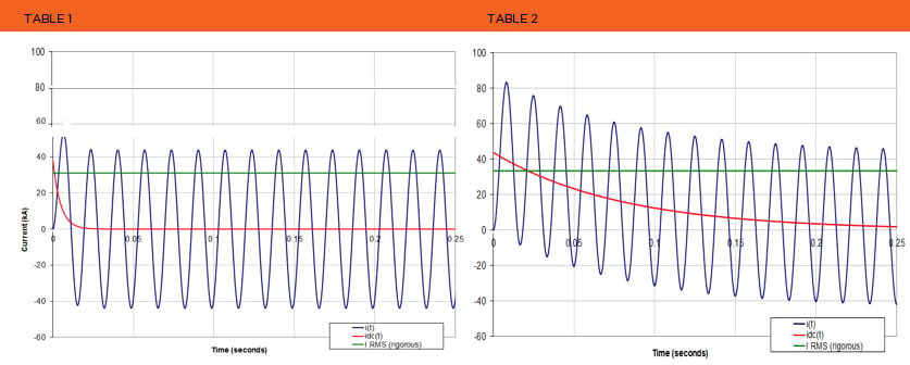
Many utilities in the past have assumed a low X/R ratio and a symmetrical current during a ground fault. However, with higher loading on the system and protective grounding locations near generation and substations, many utilities are discovering that these locations in fact have a higher X/R ratio. Remember, any X/R greater than 1.8 necessitates the use of ground sets rated to Table 2 (with the H rating). Grounding designs tested to Table 1 will not provide adequate worker protection at these higher X/R locations. All utilities should do the necessary engineering analysis to determine the X/R and current values at their grounding locations.
Please let us know how CHANCE® Lineman Grade Tools representatives can help you find solutions to your grounding needs!

Recommended Posts
.png?width=767&name=ACL-HPSUA-GR-EN-04290%20(1).png)
How Utilities Use Capacitor Banks for Volt-VAR Optimization

Common Misconceptions About URD Grounding — and What You Should Know
