3 Key Components for Proper Personal Protective Ground Set Assembly
CHANCE® Personal Protective Grounding Sets are an important tool for Linemen to use during de-energized and grounded line maintenance. The grounding sets serve two purposes; one is to provide an Equi-Potential Zone (EPZ) minimizing current flow through a lineman and the second is enabling the clearing of the fault in the fastest available time. For these two things to occur, personal protective grounding sets must be properly rated, assembled and installed. A great document to read for more information on grounding sets and equipment, including ratings, is the CHANCE Encyclopedia of Grounding. The three keys to ground set assembly are proper crimping of ferrules, installation of ground clamps, and testing.
Crimping Ferrules:
The trickiest connection in a grounding set is the cable to ferrule connection. If the crimp is too loose, the cable could pull out during a fault current and be unable to provide protection. If the crimp is too tight, grounding cable strands can become broken or damaged and increase the resistance of the grounding set. If the resistance is too high, then the grounding set may not provide adequate protection during a fault current. The goal is for the grounding set providing the parallel path to the lineman to have resistance as low as possible to ensure the majority of the fault current flows through it.
In order to properly crimp CHANCE ferrules to CHANCE grounding cable, the proper Factory recommended dies should be used. The Factory has fault current tested grounding sets to ASTM F855 with ferrules crimped on the cable using Burndy crimpers and dies, Anderson Versa-Crimp dieless style crimpers, and a Finn-Power 8-sided die crimper. The instructions for properly installing ferrules to grounding cable can be found here. Heat shrink is recommended to be applied over the cable and ferrule after crimping to help avoid contamination, moisture ingress, and provide strain relief to the cable-ferrule connection.
Installing Grounding Clamps:
Proper installation of ferrules into grounding clamps is important as it will help keep the resistance low, protect the cable termination, and ensure proper functioning of the grounding sets. For plain plug ferrule clamps, it is important to install ferrules on the cable. ASTM F855 requires ferrules to be used. The grounding cable should not be stripped and inserted into the j-bolt of the clamp without a properly crimped ferrule. Instead, a plain plug ferrule should be crimped on the cable and fully inserted into the clamp with the j-bolt tightened down to 250in.-lbs.
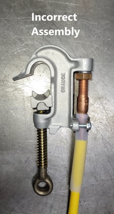
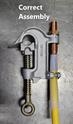
For threaded ferrule grounding clamps, it is important to use all hardware provided with the ferrules and ensure the ferrule is threaded fully into the grounding clamp. Once fully threaded, the lock washer and nut should be installed above the threaded boss in the grounding clamp and tightened to 250in.-lbs (see images below). There is one exception to the instructions above, C6000065, which has a blind threaded hole where the nut and lock washer are installed below the hole.
There are several threaded ferrule grounding clamps that are offered with drilled holes to simplify the assembly process. With these clamps, the ferrule is inserted all the way into the hole and the lock washer and nut are installed above the drilled boss and tightened to 250in.-lbs.
Following are examples of an incorrectly assembled grounding set where the lock washer and nut are installed in the wrong location (under the threaded boss) and a properly assembled grounding clamp with the ferrule fully threaded in the clamp and lock washer and nut installed above the threaded boss.
Testing:
Once assembled, the grounding set can be tested with a CHANCE Protective Grounding Set Tester. The tester measures the DC milliohm resistance of the set and the reading is then compared to the values in ASTM F2249 Table X1.3 Rmax Limits – DC Resistance (mΩ) (Cable + Terminations) or using Equation 4 in the standard. The values can also be found in the Grounding Set Tester Instructions. If the measured resistance is higher than the maximum allowed by ASTM F2249, the tester includes probes to help find the area of high resistance in the newly assembled set.
Summary:
To provide protection, personal protective grounding sets must be properly rated, assembled and installed while performing de-energized line maintenance. Always remember to follow your company’s work practice and procedures. Please reach out to your local HUS Territory Manager if you have any additional questions about CHANCE Personal Protective Grounding Equipment!
Recommended Posts

Why Raccoons Climb Transformers: A Hidden Risk in Electrical Substations

Fall Protection Safety Tips Every Lineman Should Know
