The Wild Mile: Anchored in Sustainability
The Wild Mile cleans the Chicago River with the root systems of native plants, but its sustainability story goes even deeper - all the way to its foundation.
Chicago’s Goose Island area was once an industrial center for tanneries, breweries, and soap factories. The flames from Peoples Gas Light and Coke Company on the east side of the island gave the neighborhood its nickname of "Little Hell."
Now this area is being revitalized as an urban wildlife sanctuary known as the Wild Mile.
A Brief History of the Chicago River
The Chicago River itself is a bit of an engineering marvel. In 1887 the Illinois General Assembly decided to hire civil engineers to reverse the flow of the River. Rather than dumping Chicago’s waste into Lake Michigan, they added a new canal – the Chicago Sanitary and Ship Canal, which hooked the Chicago River to the Des Plaines River, to the Illinois River, to the Mississippi River just upstream from St. Louis. The reversal of the river was named a Monument of the Millennium by the American Society of Civil Engineers.
Lake Michigan was spared the growing city’s pollution, but what happened to the Chicago River? Upton Sinclair describes the river’s pollution by the meatpacking industry in his 1906 book, The Jungle.
“Here and there the grease and filth have caked solid, and the creek looks like a bed of lava; chickens walk about on it…and many times an unwary stranger has started to stroll across and vanished temporarily.”
Industries such as meat packing were crucial to Chicago’s economy, and the Chicago River, quite literally, was at the industries’ disposal. The South Fork of the River was the primary sewer for the Union Stock Yards. The meat packing industry caused so much pollution, the River became known as Bubbly Creek.

Bubbly Creek in the 21st Century
 Last year I was in Chicago and took an architectural boat tour on the River. Much emphasis was placed on how Chicago’s older buildings were designed to be shut off from the River – no windows, certainly no homes or parks. A river view from your office or hotel was not something to brag about. It wasn’t until the 1970s and the passage of the federal Clean Water Act that things began to change.
Newer architectural designs embrace the River. The City now requires public access to the River in all parts. And of course, rather than sewage and industrial waste, the River now carries boatloads of tourists and kayakers.
Urban Rivers is a nonprofit organization that has been working since 2014 to improve environmental conditions in the Chicago River. While the river isn’t actively being polluted like it was at the turn of the 20th century, its flora and fauna are still depleted and suffering from the decades of contamination. Urban Rivers’ biggest project is the Wild Mile, the world’s first floating eco-park. The team of ecologists, entrepreneurs and volunteers who have been working to make the Wild Mile a reality are already seeing direct improvements to the area’s wildlife.
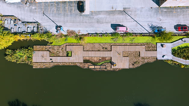
 In 2022 Urban Rivers began the Wild Mile in the Goose Island Area of the Chicago River, bringing quality wetland habitat for wildlife, both above and below the water. The roots from the native plants in the floating gardens help filter and absorb pollutants out of the water and improve the entire ecosystem. The Wild Mile is a multi-phase construction project, two of which have been completed so far. The end goal, as the name suggests, is a mile long boardwalk surrounded by native plants and trees.

Building the Wild Mile
The dock supplier connected the Urban Rivers team with Hazelett Marine of South Burlington, Vermont. Hazelett does eco-friendly mooring and marine engineering. One of the products they use is elastic rodes. When integrated into a mooring line, the Hazelett Marine Elastic Rodes provide stability and constant tension for floating structure. Tests conducted by a third-party accredited testing facility conclude that a single rode will withstand over 4,500 pounds (or 20 kN) of force. The elastic can repeatedly elongate over 200% and return to its original length.
The ability for the rodes to be able to be repeatedly stretched and relaxed is important because in a 100-year study of the river’s water depth, engineers determined that the depth had fluctuated from 5-1/4 feet to 15-1/8 feet, a difference of 9-7/8 feet. In the illustration below, you can see how the rode assembly, shown with black lines, stretches and relaxes depending on the water level.
 The bottom structure in the design was listed as mud and clay. The River is fresh water with minimal waves and a current of less than 1 knot. The docks are protected from high wind with little to no fetch. Fetch refers to the distance of open water surface over which the wind blows, which determines the size of waves that can be generated on a body of water. Using system requirements from ASCE 7-10 and data from Urban Rivers, engineers at Hazelett estimated the forces on the structure to design the rodes and foundation.
Force Calculations
The three most influential forces on a mooring system are waves, wind, and current, which are all horizontal forces. The elastic is spec’d based on expected operating parameters. Engineers calculated a worst-case scenario for all three forces to determine the limit line, or maximum allowable load, for the mooring system.
The first force calculated was the wave force, using the standard mean drift force equation. This calculates wave forces moving floating objects in the direction of the wave.
Generally, when calculating wind force for a dock, an engineer would have to include a large wind catch area due to boats moored to the structure. In the Wild Mile project this was not the case so the exposed area only took into account the dock itself.
The final force taken into consideration was current force, which is a function of pressure and area.
In both phases of the project, the system was designed for a minimum water depth of 3 feet by the shoreline at the existing steel abutment to 15 feet at the outermost dock.
 The elastic rodes are designed to work for normal operating conditions – the expected daily operation. For the worst-case scenario, limit lines are designed for use during peak loading conditions. If the elastics were sized for maximum loads, they would be way too stiff for normal loads. The downline is sized to handle 30 to 70% of the worst-case scenario and has very little stretch. If the system gets to worst-case mode, the limit line will take over, leaving less than 30% of the design load for the downline.
The mooring force equation takes the total horizontal force, which was a sum of the wave, wind, and current forces, and uses the angles of the lines once they are installed to determine the force on the lines themselves.
Anchoring the Wild Mile
 Phase 1 was a 356-foot walkway built in 7 sections. Around 35 concrete blocks weighing 3,000 pounds each were hoisted and dropped into the River for Phase 1. Although the project was engineered to allow for a water level fluctuation of 5 to 15 feet, concrete is unpredictable. Even under the relatively low forces of the Chicago River, the concrete anchors have shifted since installation and now that section of the dock is unable to be properly tensioned.
When it came time to build phase 2, the decision was made to switch the foundation type to Chance helical anchors. The anchor length was determined by doing some historical research on what the canal had originally been dug to. They determined the anchors would need to be installed to 19 feet deep to allow the helices on the lead section to be installed past the silt and sediment and be secure in load-bearing soil.
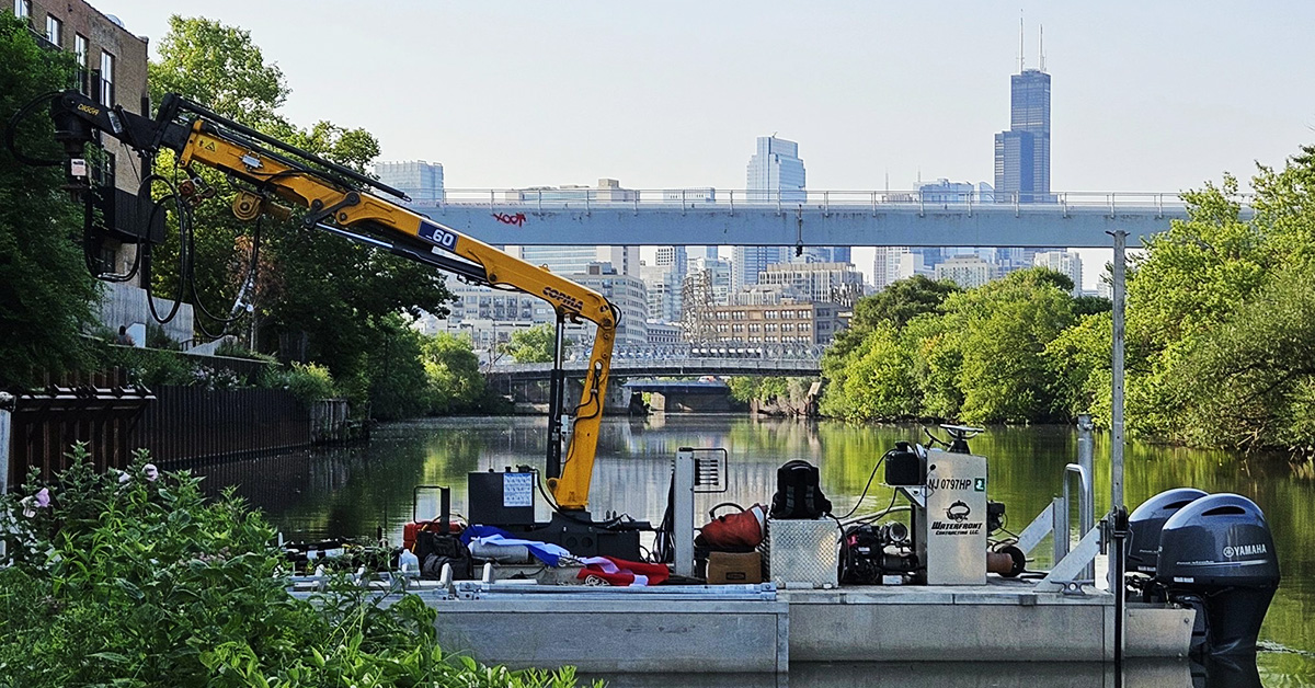
 The helical anchors were provided by Helix Mooring Systems in Cumberland, Maine and installed by Waterfront Contracting of Franklin Lakes, New Jersey. They were installed from the surface using a hydraulic torque motor mounted to a crane on a barge. A "torque hub" torque meter measured the torque during installation. After installation a diver would disconnect the anchor from the drive motor and attach the rode.
For this project they chose a Chance SS5 Anchor, which is an inch and a half solid square bar with three helices with 8, 10, and 12” diameters. Since square shaft piles have less surface area than pipe, contractors generally find them easier to install. Another advantage of square shaft is that it has the lowest cost per kip for jobs under 50 kip. Square shaft offers the highest torque-to-capacity relationship of any pile type, providing more accurate load calculations.
 Helix plates serve a two-fold purpose. Firstly, they help install the pile. They are rotated, or screwed, into the ground much like a wood screw, except that helical piles don’t have a continuous thread. Secondly, the helix plates transfer load to the soil in bearing. Helical piles are specifically designed to minimize soil disturbance without considerable displacement during installation. Keeping soil disturbance to a minimum helps to improve the load capacity of the pile. The pitch of the helix is designed so it follows its own track, keeping soil disturbance to a minimum and producing no spoils.
Why Helical Anchors?
Helical anchors are an excellent choice for mooring applications. Although concrete anchors and helical anchors have the same function, there are significant differences between them. We can see these differences most obviously in terms of design, capacity, cost, and, of course, environmental impact.
-
DESIGN: Helical pile load test data are widely available for both compression and tension applications in a variety of soil conditions. This data has been collected into software programs such as HeliCAP helical capacity design software. By entering the soil parameters, the software will calculate loads for Chance helical piles. Capacity can and should be verified by measuring installation torque and performing a load test for compression or a pull test for tension. For this project, torque was measured during installation and a pull test was performed by Waterfront Contracting. Even though loads were calculated for the concrete anchors, they still lacked the predictable capacity that you can expect with helical anchors which could be seen in the shifting that occurred after installation.
-
CAPACITY: Depending on the anchor size and soil conditions, you can anticipate holding from 1,000 to 2,500 pounds with a small round rod anchor, and upwards of 20,000 pounds with a larger square shaft anchor. Bridled together and sized accordingly, these systems can be engineered to secure even larger loads. In a pull test done in Vineyard Haven, Massachusetts, a square shaft helical anchor with two helices with 8- and 10-inch diameters were measured with a breakout force of over 20,000 pounds. A 65-foot tug pulled diagonally on each anchor until it failed and the load at failure was recorded. Actually, the Chance helical anchor never failed. Rather, the 1.5” pulling hawser parted at 20,800 lb. of load.
-
COST: Pound-for-pound, concrete can be cheaper than steel. But, as we discussed earlier, in this scenario, a 160-pound anchor outperformed a 3,000-pound concrete block, so we must look deeper. There are other costs incurred in the process of transporting and installing concrete versus helical piles. The transportation and mobilization costs are less with helical anchors. The weight difference alone can have a significant impact on life cycle cost evaluations including engine combustion gases and the fixed costs embedded in mobilized equipment. These savings are reflected both financially and environmentally. Anchors age slowly. Since most of the anchor is below ground, exposure to air or water is limited, making it an excellent long-term investment. The less often an anchor needs to be adjusted or replaced after installation, the lower the cost and the lower the carbon emissions. Concrete anchors also have a long material life; however, their ability to stay in place long-term is less reliable than a helical anchor.
Other Considerations: Net Buoyancy and Sloped Surfaces
 We all understand that when we’re underwater, we’re lighter. This is because there is an upward force on submerged objects called – net buoyancy – which applies to concrete anchors. For instance, you can start with a 3,000-pound block, but as soon as you submerge that block, you will lose 35-40% of its weight. So, in actuality, the customer may be paying for a 3,000-pound block (plus the cost and emissions of transporting) but is only getting 1,800-1,950 pounds of holding. This is not always factored into people’s cost comparisons when considering which foundation type to utilize.
Another consideration is when you are designing for a sloped surface. Concrete anchors’ holding is greatly reduced when the load is being pulled towards the downward side of the slope, even before the mooring line is attached.
For example, 14 concrete blocks weighing 5,000 pounds each were supposed to be securing an ice barrier protecting a surface salmon cage in a salmon farm. The concrete blocks had been sliding under the load of the ice pressing against the barrier so the decision was made to replace these 14 concrete blocks with 9 Chance anchors. By utilizing a deep foundation, they provided a system that stays in place, even during changing weather conditions, and does not scour the seafloor.
Environmental Benefits of Helical Anchors
 Specifically for underwater applications, when concrete anchor blocks slide, they tear up the seafloor with it, causing great damage to marine ecosystems including eelgrass and coral. For our friends at the Wild Mile, some animals, such as Chicago's celebrity snapping turtle Chonkosaurus, spend winters in a dormant state burrowed in the mud at the bottom of the river. So to them a shifting concrete block could be devastating!
 Eco-friendly helical anchors have a small footprint, screwing into the sea floor with little disturbance to the soil or marine life. Since they are embedded in stable soil, they stay put, even on a sloped bottom or when load conditions increase. The short section of exposed anchor that connects to the mooring line is not invasive or harmful to the surrounding ecosystem.
In December 2024 an article titled “Should the Industry Care About Scope 3?” by Dr. Aaron Gallant was featured in DFI Magazine. Scope 1 and 2 emissions cover the emissions directly generated from owned machines and purchased energy required to operate a manufacturing site. Scope 3, as Dr. Gallant talks about in his article, is about the supply chain and the more indirect impact our businesses have on the environment. By expanding our sustainability efforts to include Scope 3 emissions, we gather a more holistic perspective of our carbon footprint and how we can improve it.
 Here's an example of Scope 3. At Chance, all our square-shaft steel is sourced from mini-mills which use scrap to charge their melt shops. The recycled content of square shaft is nearly 100%. Chance sources all its square shaft steel from mills in the Midwest, which means fewer CO2 emissions are created to get the raw material to the manufacturing facility in Missouri. From there we strive to ship out full truckloads to our distributor network across North America. Helical piles are efficient to ship compared to many other foundation types – like the concrete blocks we talked about earlier. And by sending out full truckloads, our distributor network is mobilized to serve their local area whenever product is needed.
Another scope 3 component for helical piles involves the end-of-life treatment of sold products. Helical piles are removable and reusable. They are made from recycled steel, so they are recyclable. Helical piles can be reversed out of the ground and reused in another location.
LEED Points for Helical Piles
Leadership in Energy and Environmental Design (LEED) is a program by the US Green Building Council encouraging green building. Utilizing helical piles in foundation design may be able to gain points towards LEED certification in categories regarding sourcing, life cycle impact reduction, sensitive land protection, and more. Since helical piles can be installed with small (sometimes even portable) equipment and don’t generate spoils, they are a popular choice for environmentally sensitive areas or previously contaminated sites.
Learn more about potential sources of LEED points to be gained by using helical piles
Carbon Calculator
For solid data confirming a foundation design’s sustainability, The European Federation of Foundation Contractors and DFI created a tool called the Carbon Calculator, which is accessible online at www.geotechnicalcarboncalculator.com. It allows comparison and evaluation of the carbon footprint of foundation designs.
Click for an example of the Carbon Calculator's calculations.
Helical Anchors for Sustainable Building
You can use your engineering expertise and ingenuity to make significant contributions regionally and, from a sustainability standpoint, globally. Your actions now will affect the future. Please choose products and methods that are better – both structurally and environmentally – than just dumping concrete in a river.

Photos courtesy of Urban Rivers, Waterfront Contracting, Hazelett Marine.
Recommended Posts

How to Specify Helical Piles: A Practical Guide for Engineers

Streetlight Foundation Design: ASD vs. LRFD Explained
