The Difference Between Serviceability and Capacity of Helical Piles
Specifying the capacity of a helical pile is important, it is also necessary to design to the serviceability requirements for the structure.
The best place to start with a discussion of the difference between serviceability and capacity of helical piles is with an example about floor joists in an old house. This type of structure can have 2X8 joists spanning 12 or more feet. The floor in the center of the room could deflect more than an inch under certain conditions. This can result in no consequence at all other than all the furniture rattling around as a person walks around the room. A carpet or hardwood floor can flex and have no issue. However, that new tile floor that was just installed will crack and mortar joints will fail. The joists have the capacity to carry the load, but are not stiff enough to protect the finish floor (they are not serviceable). Helical piles and other deep foundations can have the same issue. A pile may be able to carry the load but may settle too much.
What is capacity for a Helical Pile?
The ultimate capacity of a helical pile is the maximum load the pile can resist without exceeding specified performance criteria. While there are other methods to determine ultimate capacity, the 10% offset method is typically used as the failure criterion for axially loaded end-bearing helical piles. The failure criterion is when the pile has displaced (settled) 10% of the average helix diameter. Note this is a net displacement. It does not consider the elastic deformation of the shaft. It is just a measure of the helix movement. To get the gross (total) displacement at the ultimate capacity, the elastic shortening of the shaft and any coupling slack must also be considered. For long piles, it is not uncommon for there to be over an inch of total settlement in the pile to reach ultimate capacity.
This is one reason why piles are designed with a factor of safety (FS). The displacement of the helix plates at a factor of safety of 2 is generally between ¼ and 3/8 of an inch. Since the capacity is halved, the elastic shortening is also much lower at this factored or working load. Which is where serviceability comes in.
What are serviceability requirements for Helical Piles?
The first thing to remember when discussing serviceability of any foundation element is that it will move under load. No matter if it is an H-pile, auger cast pile, drilled shaft, or helical pile, it will displace some amount. Structural engineers like to assume zero displacement of the foundation when loaded. This is impossible. For structural materials to take load, they must deflect due to their elastic nature. A person standing in a building is deflecting the beams they are standing on. The structure then transfers the load to the foundation elements that also deflect due to load. Hopefully not enough to be measured, but deflect, nonetheless. The job of a structural engineer is to determine how much displacement the structure can sustain. The max displacement the building can sustain is the serviceability requirement and is different for different structures. A residential house will have a different amount of allowable displacement compared to a skyscraper with glass façade. A transmission tower structure may be able to move upwards of 4 inches in any direction and have no lasting damage, but a house may crack the drywall at around 1/2 inch.
Once the serviceability requirement is determined, a helical pile must be designed to meet those requirements. When determining the displacement of a pile, the working or allowable loads are used. This is because the working load is the largest anticipated load the building will see.
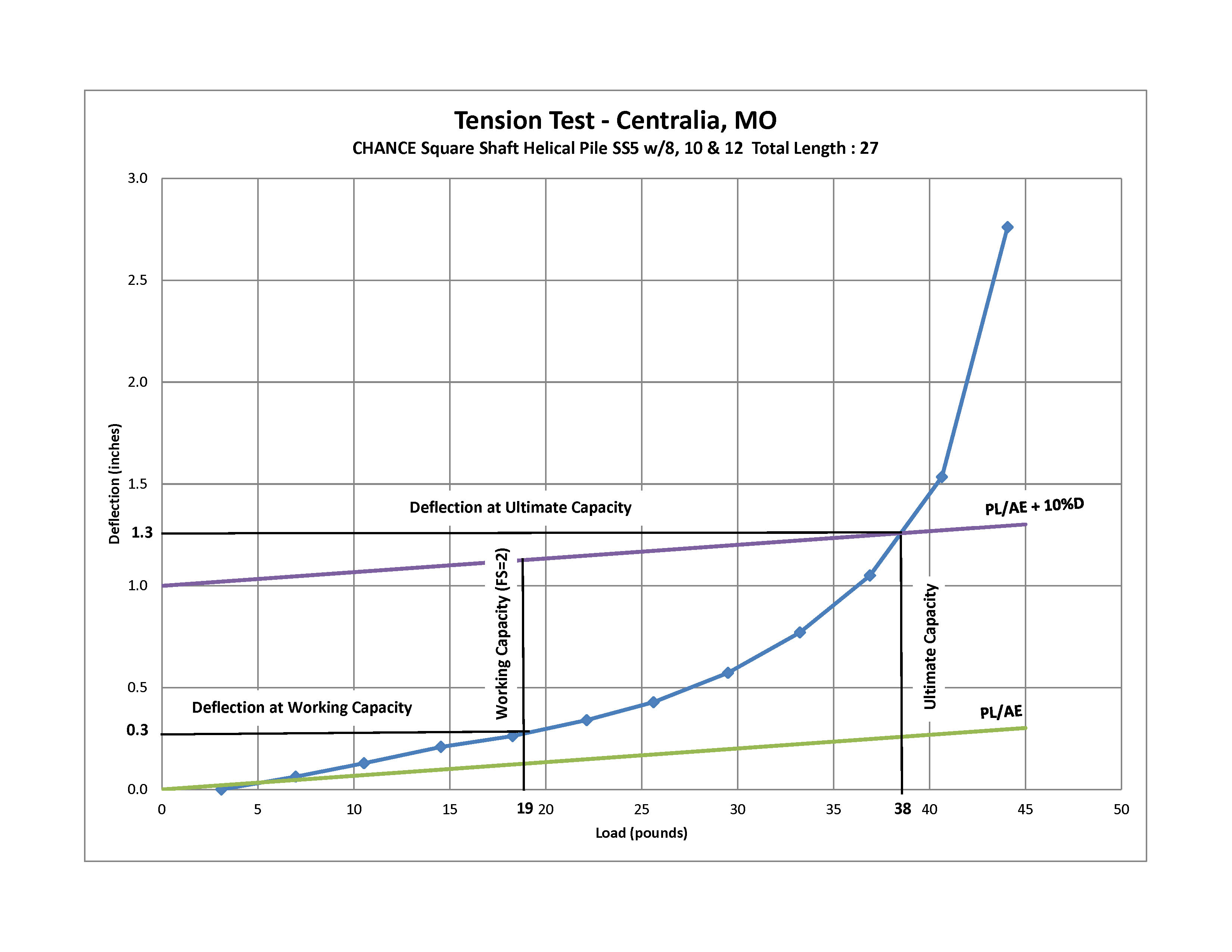
The FS (particularly its magnitude) is a measure of confidence in the capacity of the pile. Typically, helical piles are designed to a FS of 2.0 due to torque correlation while other deep foundation methods use a FS of 3.0. The plot shows a load vs displacement curve from a pile test. The displacement at ultimate capacity (failure) is around 1.3” for the pile tested. The displacement for the same pile at the working capacity using a FS of 2.0 is 0.3”. Again, the working loads are the loads the building will apply to the pile and thus the load for which the serviceability requirement must be met.
Ways to reduce displacement and increase serviceability
It is very common for the capacity of the pile be adequate, but the anticipated displacement be too large. This is particularly an issue on deep piles (upwards of 50 ft in length). Here are a few ways to reduce the anticipated displacement when this is the case.
-
Use a larger shaft (whether using larger diameter or thicker wall sections). This is the easiest way from a design perspective. Increasing the area of the shaft will reduce the amount of elastic deformation in the pile and result in smaller displacements.
-
Reduce the helix size and use more helix plates. While this seems counter intuitive, the larger the helix, the more the soil has to displace to mobilize the ultimate capacity and the further the helix itself flexes. Reducing the average helix size reduces the displacement needed to mobilize soil capacity.
-
Grout the ID (inside diameter) of a pipe or pulldown a grout column around the outside of the shaft are other options to reduce the elastic deformation of the shaft. This steel and grout composite shaft increase the area and result in less displacement. It also ensures there is no slop in the couplings for reversing loads.
-
Install the pile to a higher capacity. As could be seen from the load vs displacement plot, the higher the capacity the larger the displacement. If a pile has a higher ultimate capacity (installed to a larger FS), it will have less deflection at the working loads.
Additional reading: Comparing the Displacement of Pipe Shaft Helical Piles
Conclusion
A helical pile can carry large loads but may deflect more than the structure can sustain under load. While specifying the capacity of a helical pile is important, it is also necessary to design to the serviceability requirements for the structure. Some ways to reduce the displacement of a helical pile include increasing the shaft size/wall thickness or adding grout.
To learn more about designing foundations with CHANCE helical piles or Atlas Resistance piers, download the Civil Technical Design Manual.

Recommended Posts

How to Specify Helical Piles: A Practical Guide for Engineers

Streetlight Foundation Design: ASD vs. LRFD Explained
