Streetlight Foundation Design Streamlined with Engineering Software
With variables such as loading, mounting height, and wind speeds, engineering a streetlight foundation design can get complicated! We offer resources to help.
Streetlight foundation design seems complicated. How are the loads calculated? What affects loading? What about the foundation design? This is where Hubbell Power Systems, Inc. comes in to assist the engineer or specifier with the design of steel base foundations with the Pole Load Data Sheet (PLDS) and Select-A-Base™ application software. Select-A-Base is used to determine the required diameter and length for the steel base foundation.
Gathering Pole Information
This is where the PLDS is helpful. It lists what information is needed to estimate the wind load on the pole and luminaire(s). Some of the items listed on the PLDS can be found on the cut sheets/shop drawings of the pole and luminaire. Examples of this information include:
- Effective Projected Area (EPA) of the luminaire
- How tall the pole is
- Shape of the pole
- Type/size of arm (if any), etc.
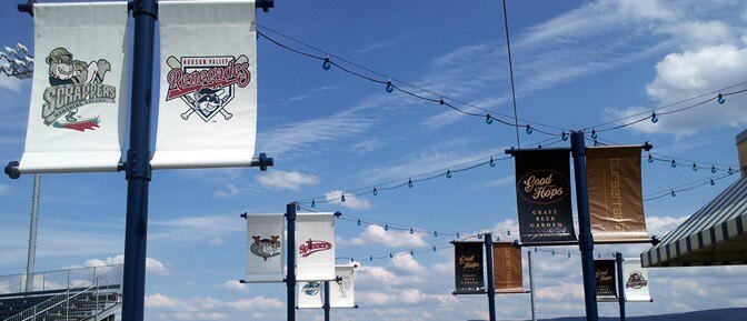
- Any banners, solar panels, etc. that will be added to the pole
All these items affect the loading on the pole.
There is also site-specific information needed to run the calculations for Select-A-Base. The Applied Technology Council (ATC) hazards by location website is a good resource to use when determining the wind speed to design for (Note: the wind speed Select-A-Base is intended for is the ASCE 7-05 wind speed).
With all information gathered, it is time to start using Select-A-Base!
Select-A-Base—What it does
Select-A-Base takes the information from the PLDS and calculates the wind loading for the pole per AASHTO 2013 – Standard Specifications for Structural Supports for Highway Signs, Luminaires, and Traffic Signals – 6th Edition (which is why ASCE 7-05 wind loading is typically used). Once it calculates the shear and moment loads, it then uses the Brom’s Method to determine the capacity of different diameters and lengths of streetlight steel base foundation in both a 1000 psf cohesion clay soil and a 30⁰ friction angle sand soil (with water table below toe of foundation). The capacities are then divided by the loads to determine a factor of safety of the steel base foundation.
Select-A-Base also checks the structural capacity of the foundation. The largest bending moment on a streetlight steel base foundation will typically occur about 1 ft below grade. This also happens to be where the cableway opening is located on the steel foundation. Select-A-Base compares the structural capacity at the cableway and max bending moment from Brom’s) to ensure the steel foundation has the required structural strength.

Results
After all the inputs are entered and Select-A-Base has run its calculations, it will bring up the results page. This page is where a designer decides what steel foundation to use. The page will be broken into two charts. One is the 1000 psf cohesion clay soil and the other is the 30° sand soil.
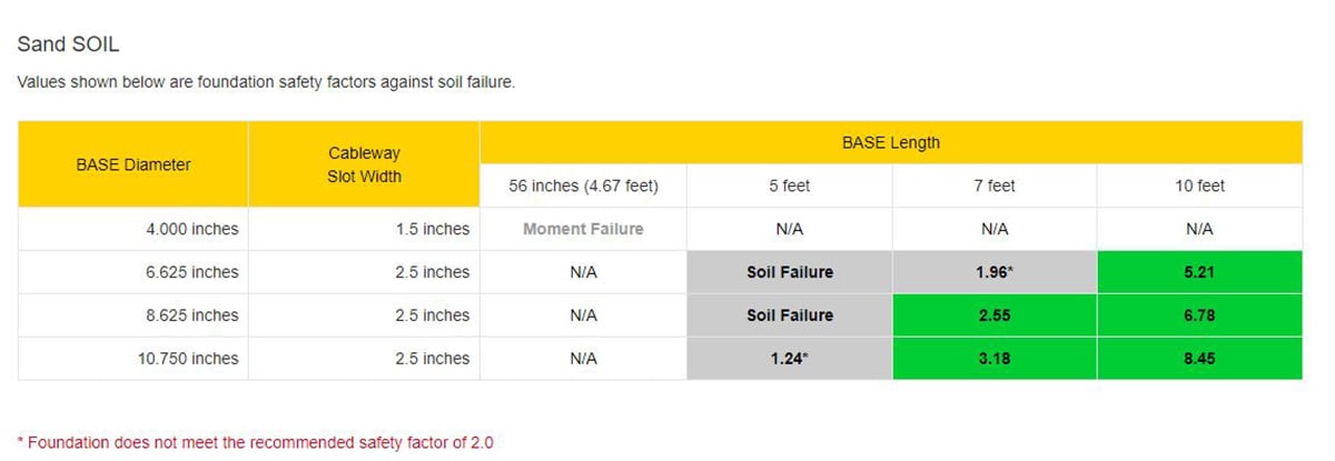
Typically, Hubbell Power Systems, Inc. engineers recommend using a minimum Factor of Safety (FS) of 2.0 for steel foundation design. All results with a minimum FS of 2.0 will be highlighted in green and the FS written in the box. If the box is highlighted grey, the Factor of Safety is between 1.0 and 2.0. If the box says “Soil Failure” or “Moment Failure” the steel foundation will fail under the loading calculated.
Design Considerations
Here are a few words of advice when selecting streetlight steel base foundations:
-
-
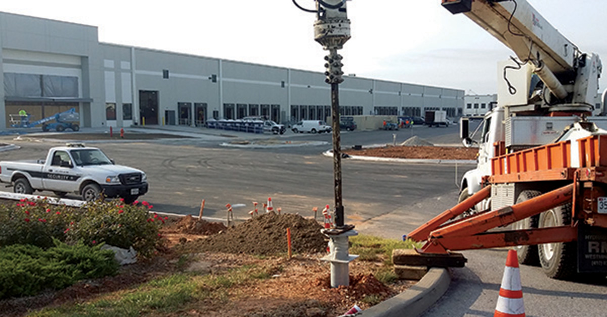
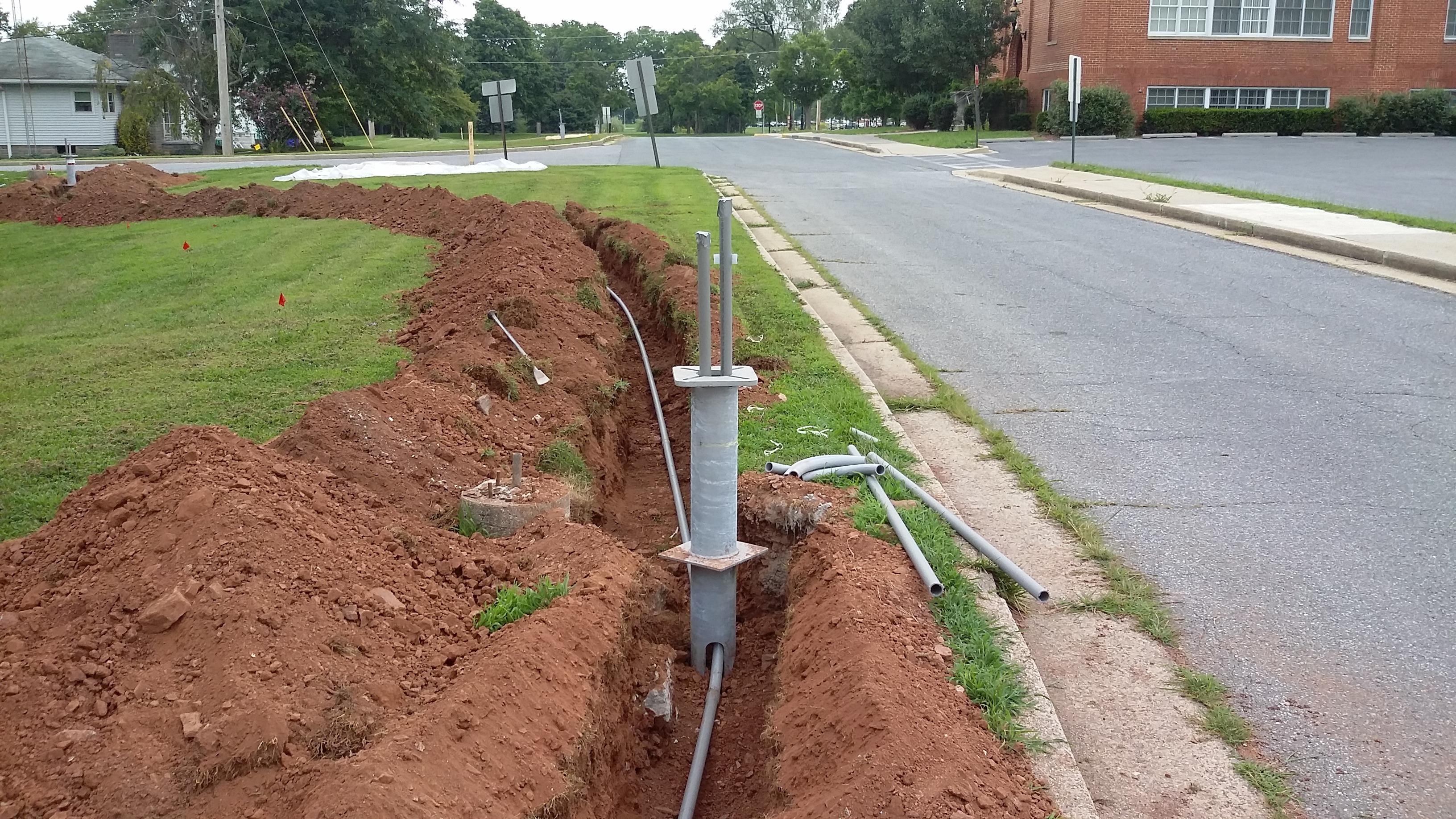
- A 10ft or longer steel foundation should be avoided if possible due to ease of installation and higher cost. If a 10” dia x 7 ft long steel foundation works, it is typically easier to install than a 6” dia x 10 ft long foundation. This has to do with the fact that the foundation has to be connected to the drive motor while standing vertically. Unless a contractor has a 7ft tall NBA player working on the crew, the ground person will have to be on a ladder or truck bed to connect the 10ft foundation to the tool/Kelly bar.
- If a streetlight pole is over 15 ft tall, it is recommended to use a minimum 6” dia x 4ft foundation rather than a 4” dia x 56”. The smaller foundation has been known to allow the pole to wobble a little in actual use. While it has the capacity, the deflection at lower loads is larger than what most people are comfortable with. Think of when you see a tree’s branches moving in the wind. The branches can move a lot and still be fully perfectly fine, but most people give the tree a wide berth while it is happening.
- There are several scenarios when Select-A-Base cannot assist in steel base foundation design. Those scenarios include when the soil is softer than 1000 psf cohesion clay, when the ground water table is shallow, i.e. not below the toe of the foundation, and when a banner or solar panel is attached to the pole. If any of these situations apply, our engineering team is happy to run the load and capacity calculations and provide a steel base foundation design for your consideration.
- A 10ft or longer steel foundation should be avoided if possible due to ease of installation and higher cost. If a 10” dia x 7 ft long steel foundation works, it is typically easier to install than a 6” dia x 10 ft long foundation. This has to do with the fact that the foundation has to be connected to the drive motor while standing vertically. Unless a contractor has a 7ft tall NBA player working on the crew, the ground person will have to be on a ladder or truck bed to connect the 10ft foundation to the tool/Kelly bar.
-
Important Resources
👉 Click to start using Select-A-Base application software: https://www.hpsapps.com/base.
👉 Get the Pole Load Determination Data Sheet
Recommended Posts

Seven Frequently Asked Questions about Helical Piles

How to prevent copper wire theft from light poles
