Gapped vs Gapless Distribution Arresters
These arresters might look identical from the outside, but the different internal module design affects how the arrester protects voltage sensitive equipment. Read our blog to learn more about the difference between gapped vs gapless distribution arresters.
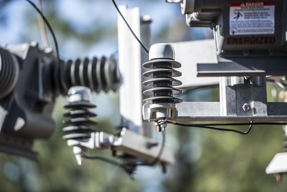
When comparing different arrester designs, it is important to understand how the arrester was built to correctly evaluate the amount of protection it will provide. The IEEE C62.11 standard covers two types of Metal Oxide Varistor (MOV) distribution arresters that are available today, internally gapped and gapless. These arresters might look identical from the outside, but the different internal module design affects how the arrester protects voltage sensitive equipment.
The gapless arrester module is created with a solid stack of MOV discs and conductive materials where the gapped version utilizes less MOV material and contains a gap structure. If the gap is ungraded, this design can reduce the power loss of an arrester while sacrificing the protective margin achieved between the arrester protective level and the BIL of the equipment being protected.
The protective level of an arrester is voltage the equipment sees during a surge, so lower is better for long-term protection. For a gapless arrester protective level and discharge voltage can be used interchangeably. Because lightning discharge by an internally gapped arrester does not begin until after the gap sparks over, IEEE C62.11 defines protective level differently. Gapped arrester’s protective level is ultimately the higher of gap sparkover voltage or discharge voltage.
The IEEE C62.11 standard specifies additional testing required for gapped arresters to verify the long-term stability of the arrester. Customers considering the gapped design should have access to this data through the arrester manufacturer.
Arrester design tests are used to prove an arrester product line meets the requirements set by the arrester standard.
Additional design tests required for gapped distribution arresters:
- 8.3 – Power Frequency Sparkover
- 8.4 – Impulse Protective Level
- *8.13 – Low Current Long Duration Withstand
- *8.16 – Duty Cycle
- *8.17 – Temporary Overvoltage (TOV)
*IEEE C62.11 specifies sparkover verification is necessary to confirm the gap structure is not damaged
Arrester routine tests should be performed on every arrester made by the manufacturer. Customers can access data related to their order by requesting the Certified Routine Test Report.
Additional routine tests that may be required for gapped distribution arresters:
- 12.4 – Seal Test
- 12.6 – Power Frequency Sparkover

Recommended Posts
.png?width=767&name=ACL-HPSUA-GR-EN-04290%20(1).png)
How Utilities Use Capacitor Banks for Volt-VAR Optimization

Common Misconceptions About URD Grounding — and What You Should Know
