Low-Deflection Design to Protect MRI Equipment
Helical piles prove to be an excellent choice for this hospital design with sensitive equipment, no vibrations, and low settlement allowances.

An MRI is a highly sensitive imaging tool, crucial to the team at the Moncrief Cancer Institute in Fort Worth, Texas. One of America’s leading cancer centers, Moncrief Cancer Institute needed a foundation for its new MRI scan room that once installed would carry the design load with almost no deflection (or movement) of the piles. A person wouldn’t be able to detect if their foundation was moving slightly, but the MRI would. The allowable deflection under design load for this new construction was only 1/8 of an inch!
The room to house the new equipment was demolished and cleared out. The piles were to be installed as if it were a new construction foundation inside an existing building. The limited access installation space with existing building surrounding would need a foundation solution that wouldn’t cause vibrations during the installation and would provide a virtually deflection-free space when the MRI machine was later installed.
The MRI manufacturers required that the MRI slab be level within +/- 1/16". Therefore, the piers would need to have a maximum long-term settlement of 1/8" (to allow for a maximum differential settlement of 1/16") so that the slab would stay within the manufacturer's requirements for levelness.
Engineering the Foundation
 As with any helical foundation job, it was important for engineers to first understand two key pieces of information: the soils and the loads.
The Soils:
The geotechnical engineers conducted soil borings and found that the upper fill material was present in all borings with depths up to 7’-0. The borings showed very stiff to hard clay from the below the upper fill material to the depth of the weathered shale. The depth of the weathered shale varied from approximately 17’ to 25’. Below the weathered shale, shale and/or limestone was noted with high N-values (100 plus). The penetration of the helices into this shale and/or limestone was highly unlikely to impossible. Therefore, it was decided that the estimated bearing capacities of the helices would be based on placing the helices in the weathered shale layers.
The Loads:
The following design (working) compression (DL) loads per helical pile were determined to be:
DL1 (Dead + Live Load) = 15.0 kips
DL2 (Dead + Live Load) = 25.0 kips
A factor of safety of 2.0 was included for this permanent application. Engineers used HeliCAP®, the helical capacity design software that allows jobsite soil data to be input into the program to generate the ultimate compression bearing capacity of the selected helical piles.
Preparing for Installation
 Helical trial probes were conducted to verify the ability to install the piles into into the weathered shale and to verify that the minimum pile depths given below can be achieved without exceeding the torque rating of the helical pile shaft.
Since installation torque directly correlates to capacity, it was important that the installers could measure and verify the torque calculated by the geotechnical engineers.
From Ideation to Installation
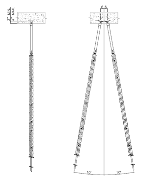
After all of the meticulous (and necessary) planning, the design was ready to go from drawings to dirt. The installation team put in 15 helical piles to an average depth of 30 feet into the weathered shale.
Grout was added around the pile shafts to accommodate the uplift design load of 46.0 kips (including the 2.0 FS). The Chance Helical Pulldown Micropile allows grout to be gravity fed into a void created around the pile by a digger plate.
Torque was monitored during the installation to confirm the calculated load requirements.
Installation was successful and the foundation proved to function as designed, providing the stable, vibration-free base required for precise imaging.
Recommended Posts

How to Specify Helical Piles: A Practical Guide for Engineers

Streetlight Foundation Design: ASD vs. LRFD Explained
