Compression Testing a Helical Pile in Less-Than-Ideal Conditions
A great benefit of helical piles is their ability to be proven with a load test in the field. I once was asked to complete a compression test on a helical pile in a remote area of Mato Grosso, in west-central Brazil.
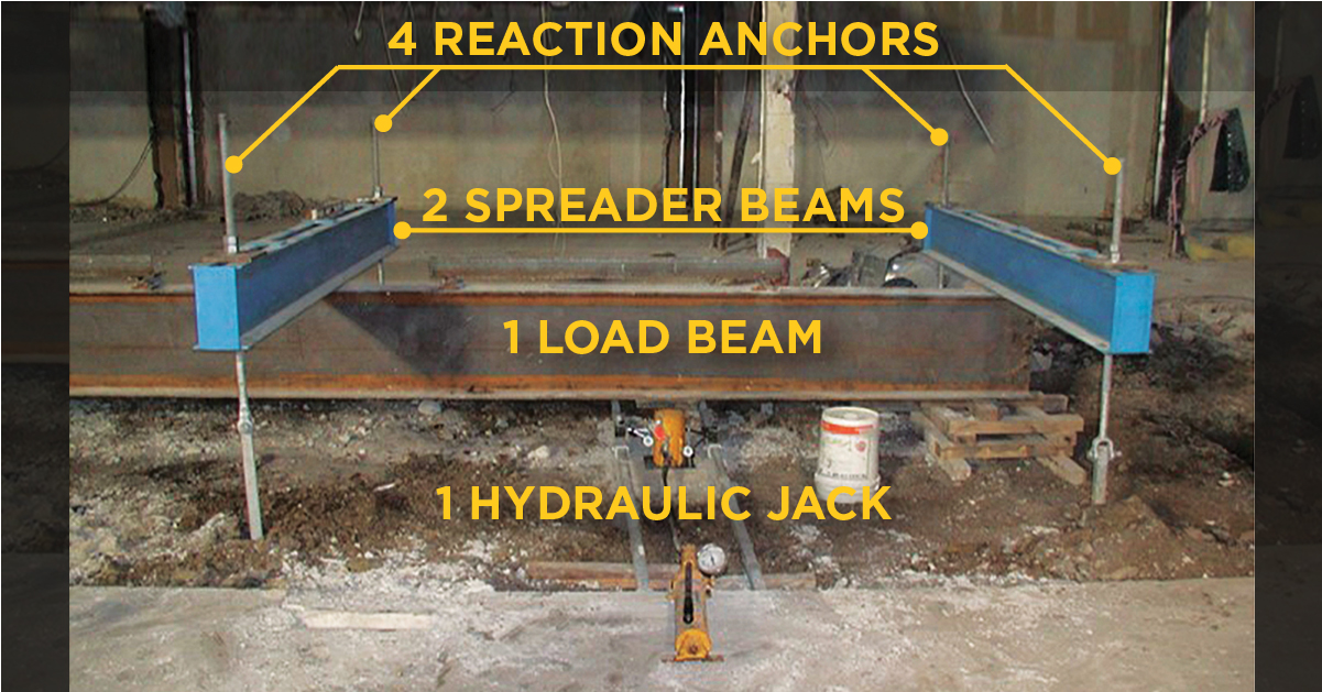
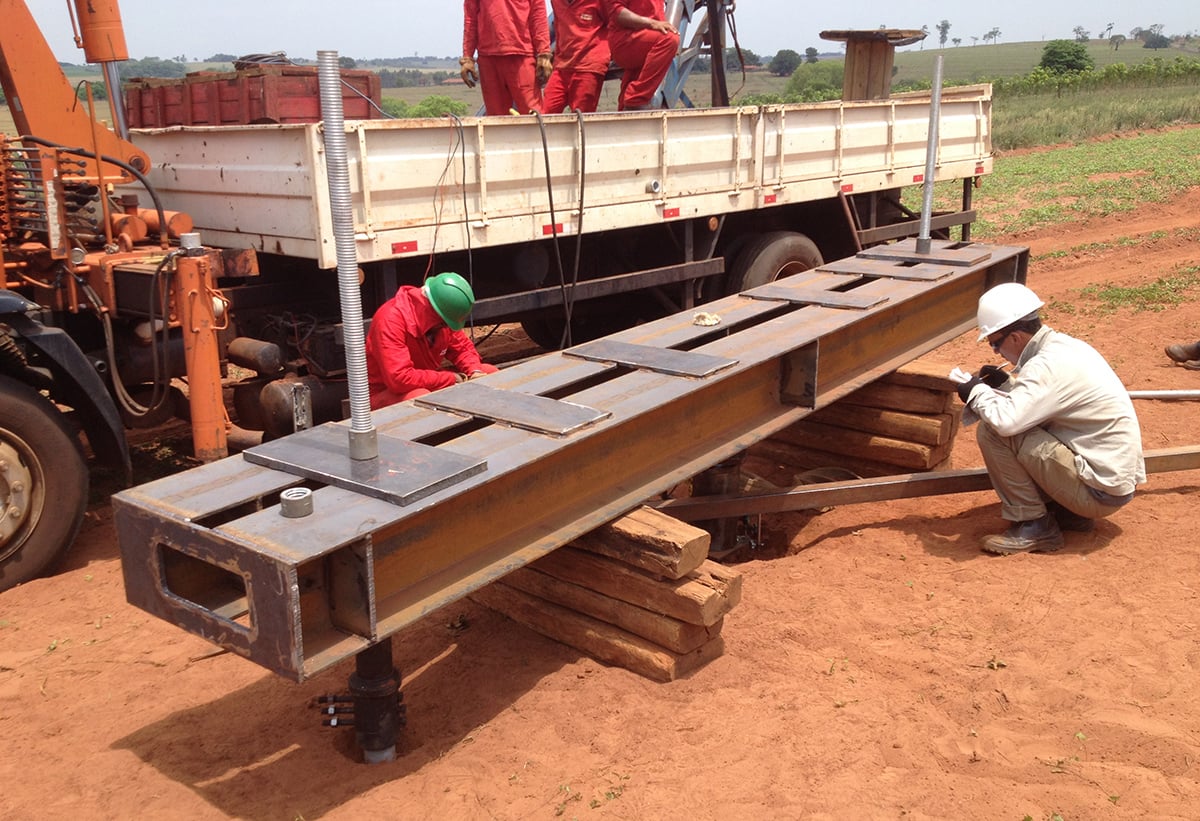
As you will read, the compression test set-up posed several challenges that could be prevented with proper information and training, which is why I’d like to share my experience. Before discussing challenging conditions for a compression test, let’s first look at what is the best-case-scenario or optimum conditions to test a helical pile in compression (See photo above).
The optimum conditions for a helical pile compression test
- The helical pile is installed vertically, perpendicular to the ground.
- The load beam should be low to the ground, straight (not bent or twisted) and level.
- 4 reaction anchors installed vertically with their combined capacity at least double the test pile’s expected ultimate capacity.
- The reaction anchors have a threaded rod termination with a standard UNC thread (a finer thread than either Dywidag or William’s Form all-thread bar) so that they can be easily preloaded by simply tightening the nuts on top of the spreader beams.
- Two separate reference beams, both independent of the test frame with dial indicators located on opposite sides of the test pile measuring test pile deflection.
- The testing procedure per ASTM D1143 Standard Test Methods for Deep Foundations Under Static Axial Compressive Load – Procedure A: Quick Load Test.
This is the gold standard for compression tests.
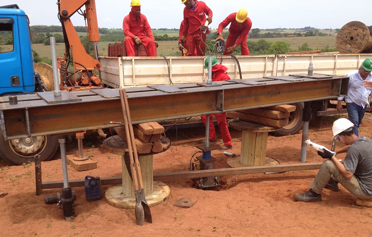
My actual in-the-field test experience
The test setup had been completed before I arrived on-site. One obvious challenge was the language barrier: I am a native English speaker and the Brazilians spoke Portuguese. Most foreign language phrase books don’t include phrases like “reaction anchor” or “threaded rod”! Thankfully, one person in our group spoke some English in addition to his native Portuguese, so we were able to get by.
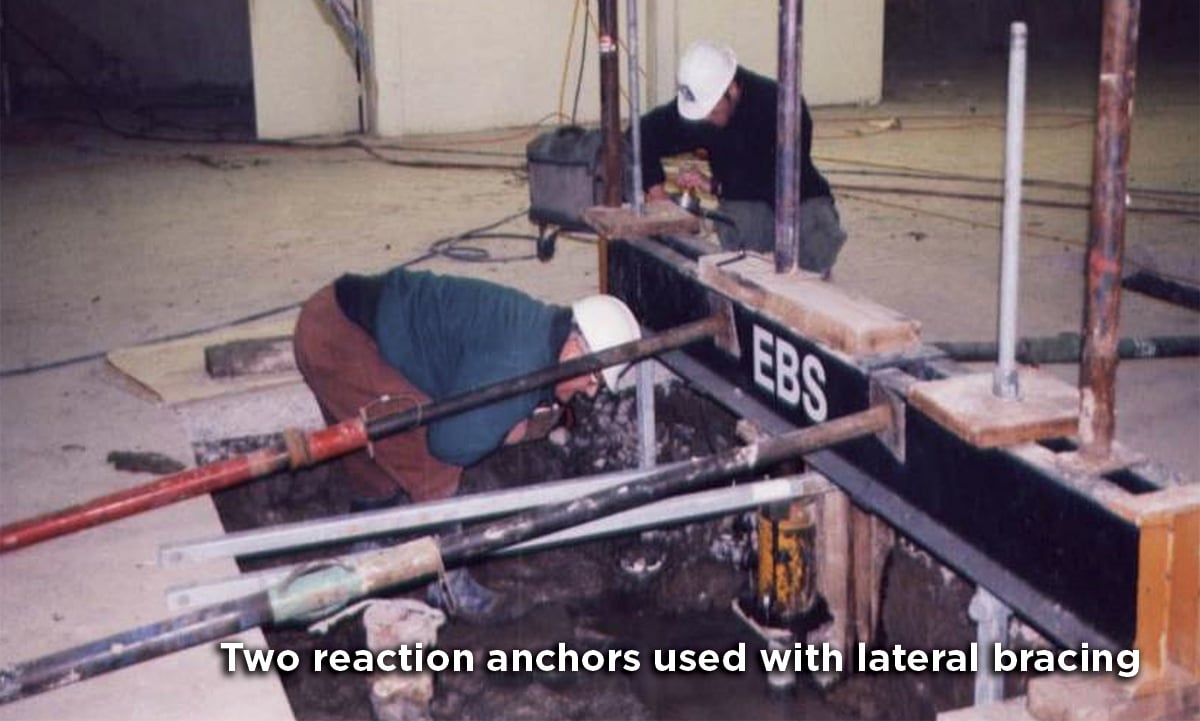
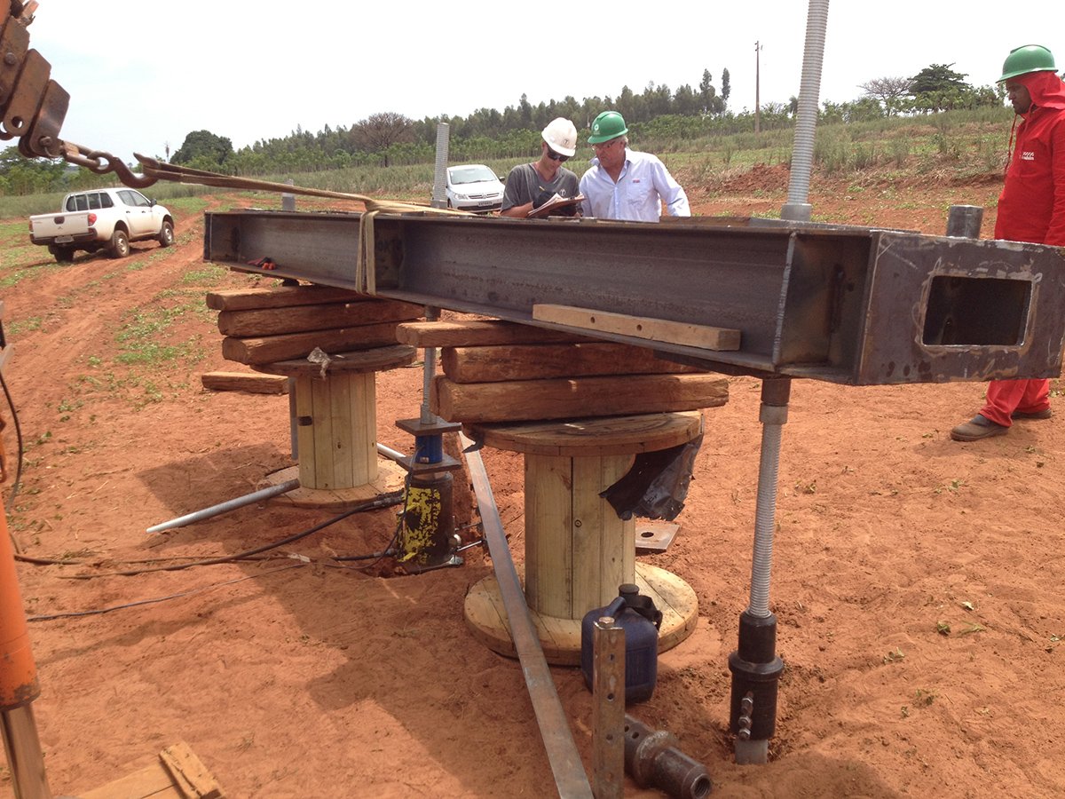 The reaction to the compression load was provided by just 2 anchors and the test pile was about 4-inches out-of-line with the 2 reaction anchors. This misalignment induces bending or rotation into the top of the test pile as load is applied. Another problem, there was about 14-inches between the hydraulic cylinder, applying load to the test pile, and the load beam. This distance was taken up with a piece of 2-inch threaded rod that extended through the beam with a nut and bearing plate placed above and below the beam.
Based on my experience doing compression tests, I didn’t expect it to work but the engineer on-site wanted to try it anyway. Before 5,000 lb was applied, the test was stopped because the load beam was rotating to a position that was unsafe to continue. The engineer told me that I would re-test the pile the next day.
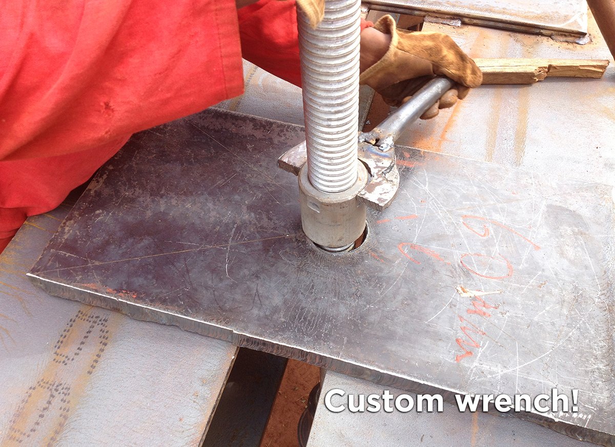
My first request was for a wrench so that I could apply torque to the nuts on reaction anchors to preload the reaction anchors. I was told they didn’t have a wrench large enough to fit the round nuts. I told them I needed a wrench to have any chance of adequately loading the test pile. The next morning, the mechanic had made me a wrench! He cut the shape from a piece of 3/8-inch steel plate with an acetylene torch and had filed the contact surface to the correct dimension and then welded a small pipe to it for a handle. He had also filed flats on the round nuts. I now had a wrench.
Next, I lowered the beam so that it was just above the hydraulic cylinder. I tightened the round nuts on the reaction anchors with my new wrench to preload the reaction anchors. I also added wood timber bracing to provide additional lateral support to prevent the load beam from rotating. The result was a stable reaction frame to jack against, which is key for a successful test.
The compression test was then completed, this time without problems. Out of hundreds of completed pile tests, I still consider this test my most challenging. To successfully test a helical pile in compression that had been previously tested and failed laterally due to rotation, I knew it was my lucky day!
Other things that can help a compression test:
If a load cell is not available, a hydraulic cylinder (a.k.a. hydraulic jack) can be calibrated to convert pressure to applied load. If measuring load by this method, the hydraulic pump, gauge, and cylinder must be calibrated together as a system.
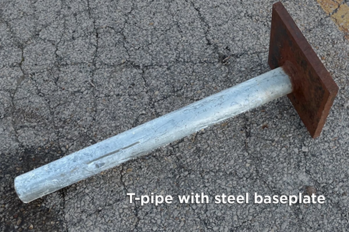
The normal end condition for the pile head is embedment in a concrete pile cap; but for testing purposes, the pile head often isn’t restrained adequately against rotation and translation. For a slender square shaft helical pile, I use a T-pipe with 12 x 12 x 1 (inches) steel baseplate with a heavy wall pipe welded perpendicular to the plate (see photo). This stiffens the top of the pile to provide a better end condition. The hydraulic cylinder can be centered on the baseplate with room for the dial indicator stems, used to measure deflection, located on the corners of the baseplate. This T-pipe will help reduce pile head rotation so that a successful test can be performed.
Also, use wax on threads of reaction anchor terminations. This will reduce the friction on threads. I have found it works better than grease and will allow more preload on the reaction anchors. More preload on reaction anchors results in a more stable test frame to jack against.
Use 4 reaction anchors if possible. When using only 2 reaction anchors, the reaction anchors and the test pile need to be aligned. Apply as much preload on the reaction anchors as possible. With only 2 reaction anchors, lateral bracing of the test frame can stop the test pile from rotating and allow a successful test.
The load beam above the test pile must be level in both directions. I have used a beam that was bent as well as twisted for a compression test only because nothing better was available. The section of load beam above the test pile still needs to be level in both directions. It may look a little crazy, but it will still function adequately.
Next steps for a successful field test
You can learn more about load tests in Appendix B of the CHANCE Technical Design Manual.
Our engineering team has a lot of experience working with helical piles and performing load tests. If you have any questions about load tests you can email us or reach out to us via your local distributor.
Recommended Posts

Maintaining Load During a Helical Pile Compression or Tension Test

A Grasp of Grout: Helical Pulldown® Micropiles vs GroutForce™ Displacement Piles
